

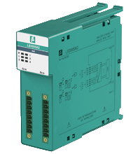
HART Transmitter Power Supply, Input Isolator LB3005A2
- 4-channel
- Power supply for 2-wire transmitters with 4 mA ... 20 mA
- Installation in Zone 2 or safe area
- Supply circuit 15 V (20 mA)
- Input from active signals of 4-wire transmitters
- HART communication via field bus or service bus
- Simulation mode for service operations (forcing)
- Line fault detection (LFD): one LED per channel
- Permanently self-monitoring
- Module can be exchanged under voltage


Please note: All product-related documents, such as certificates, declarations of conformity, etc., which were issued prior to the conversion under the name Pepperl+Fuchs GmbH or Pepperl+Fuchs AG, also apply to Pepperl+Fuchs SE.
Uddrag af datablad: Tekniske data for LB3005A2
| Slots | ||
|---|---|---|
| Occupied slots | 2 | |
| Supply | ||
| Connection | backplane bus | |
| Rated voltage | 12 V DC , only in connection with the power supplies LB9*** | |
| Power dissipation | 1.5 W | |
| Power consumption | 2.7 W | |
| Internal bus | ||
| Connection | backplane bus | |
| Interface | manufacturer-specific bus to standard com unit | |
| Analog input | ||
| Number of channels | 4 | |
| Suitable field devices | ||
| Field device | pressure converter | |
| Field device [2] | flow converter | |
| Field device [3] | level converter | |
| Field device [4] | Temperature Converter | |
| Field device interface | ||
| Connection | 2-wire transmitter | |
| Connection [2] | 3-wire transmitter | |
| Connection [3] | 4-wire transmitter | |
| Connection | 2-wire transmitter (HART): Supply circuit: channel I 1+, 2-, channel II 5+, 6-, channel III 9+, 10-, channel IV 13+, 14- 3-wire transmitter: Supply circuit: channel I 1+, 4-, channel II 5+, 8-, channel III 9+, 12-, channel IV 13+, 16- Measurement loop: channel I 3+, 4-, channel II 7+, 8-, channel III 11+, 12-, channel IV 15+, 16- 4-wire transmitter (powered externally): Measurement loop: channel I 3+, 4-, channel II 7+, 8-, channel III 11+, 12-, channel IV 15+, 16- | |
| Transmitter supply voltage | min. 15 V at 20 mA ; 21.5 V at 4 mA | |
| Input resistance | 15 Ω | |
| Conversion time | max. 100 ms | |
| Line fault detection | can be switched on/off for each channel via configuration tool , configurable via configuration tool | |
| Short-circuit | factory setting: > 22 mA configurable between 0 ... 26 mA | |
| Open-circuit | factory setting: < 1 mA configurable between 0 ... 26 mA | |
| HART communication | yes | |
| HART secondary variable | no | |
| Transfer characteristics | ||
| Deviation | ||
| After calibration | 0.1 % of the signal range at 20 °C (68 °F) | |
| Influence of ambient temperature | 0.1 %/10 K of the signal range | |
| Resolution | 12 Bit (0 ... 26 mA) | |
| Refresh time | 100 ms | |
| Indicators/settings | ||
| LED indication | Power LED (P) green: supply Diagnostic LED (I) red: module fault , red flashing: communication error , white: fixed parameter set (parameters from com unit are ignored) , white flashing: requests parameters from com unit Status LED (1-4) red: line fault (lead breakage or short circuit) |
|
| Coding | optional mechanical coding via front socket | |
| Directive conformity | ||
| Electromagnetic compatibility | ||
| Directive 2014/30/EU | EN 61326-1:2013 | |
| Conformity | ||
| Electromagnetic compatibility | NE 21:2007 | |
| Degree of protection | IEC 60529:2000 | |
| Environmental test | EN 60068-2-14:2009 | |
| Shock resistance | EN 60068-2-27:2009 | |
| Vibration resistance | EN 60068-2-6:2008 | |
| Damaging gas | EN 60068-2-42:2003 | |
| Relative humidity | EN 60068-2-78:2001 | |
| Ambient conditions | ||
| Ambient temperature | -40 ... 60 °C (-40 ... 140 °F) , 70 °C (non-Ex) | |
| Storage temperature | -40 ... 85 °C (-40 ... 185 °F) | |
| Relative humidity | 95 % non-condensing | |
| Altitude | max. 2000 m | |
| Shock resistance | shock type I, shock duration 11 ms, shock amplitude 15 g, number of shocks 18 | |
| Vibration resistance | frequency range 10 ... 150 Hz; transition frequency: 57.56 Hz, amplitude/acceleration ± 0.075 mm/1 g; 10 cycles frequency range 5 ... 100 Hz; transition frequency: 13.2 Hz amplitude/acceleration ± 1 mm/0.7 g; 90 minutes at each resonance |
|
| Damaging gas | designed for operation in environmental conditions acc. to ISA-S71.04-1985, severity level G3 | |
| Mechanical specifications | ||
| Degree of protection | IP20 when mounted on backplane | |
| Connection | removable front connector with screw flange (accessory) wiring connection via spring terminals (0.14 ... 1.5 mm2) or screw terminals (0.08 ... 1.5 mm2) |
|
| Mass | approx. 150 g | |
| Dimensions | 32.5 x 100 x 102 mm (1.28 x 3.9 x 4 inch) | |
| Data for application in connection with hazardous areas | ||
| Certificate | BVS 12 ATEX E 105 X | |
| Marking |  II 3 G Ex nA [ic] IIC T4 Gc II 3 G Ex nA [ic] IIC T4 Gc |
|
| Galvanic isolation | ||
| Input/power supply, internal bus | safe electrical isolation acc. to EN 60079-11, voltage peak value 375 V | |
| Directive conformity | ||
| Directive 2014/34/EU | EN IEC 60079-0:2018+AC:2020 EN 60079-11:2012 EN 60079-15:2010 |
|
| International approvals | ||
| ATEX approval | BVS 12 ATEX E 105 X | |
| IECEx approval | IECEx BVS 12.0055X | |
| Approved for | Ex nA [ic] IIC T4 Gc | |
| General information | ||
| System information | The module has to be mounted in appropriate backplanes (LB9***) in Zone 2 or outside hazardous areas. Here, observe the corresponding declaration of conformity. For use in hazardous areas (e. g. Zone 2 or Zone 22) the module must be installed in an appropriate enclosure. |
|
| Supplementary information | EC-Type Examination Certificate, Statement of Conformity, Declaration of Conformity, Attestation of Conformity and instructions have to be observed where applicable. For information see www.pepperl-fuchs.com. | |
Classifications
| System | Classcode |
|---|---|
| ECLASS 13.0 | 27210120 |
| ECLASS 12.0 | 27210101 |
| ECLASS 11.0 | 27210120 |
| ECLASS 10.0.1 | 27210120 |
| ECLASS 9.0 | 27210120 |
| ECLASS 8.0 | 27210120 |
| ECLASS 5.1 | 27210120 |
| ETIM 9.0 | EC001485 |
| ETIM 8.0 | EC001485 |
| ETIM 7.0 | EC001485 |
| ETIM 6.0 | EC001485 |
| ETIM 5.0 | EC001485 |
| UNSPSC 12.1 | 39121008 |
Details: LB3005A2
Datasheet: LB3005A2
| Datasheet | Fil type | Fil størrelse |
|---|---|---|
| Datasheet LB3005A2 | 706 KB | |
| Datenblatt LB3005A2 | 707 KB |
Documents: LB3005A2
CAD+CAE: LB3005A2
| CAD | Fil type | Fil størrelse |
|---|---|---|
| CAD 3-D / CAD 3-D | STP | 2141 KB |
| CAD Portal / CAD Portal | LINK | --- |
Approvals+Certificates: LB3005A2
| Certificates | Fil type | Fil størrelse |
|---|---|---|
| Brasil TUV Rheinland Brazil | 637 KB | |
| Bureau Veritas (Maritime) Marine | 590 KB | |
| China SITIIAS CCC Ex Certificate | 2657 KB | |
| DEKRA EXAM IECEx Certificate of Conformity | LINK | --- |
| DNV Marine | 110 KB | |
| Europe DEKRA EXAM ATEX Category 3 G | 2912 KB | |
| Lloyd's Register Marine | 557 KB | |
| South Africa MASC | 730 KB | |
| Declaration of Conformity | ||
| EU Declaration of Conformity (P+F) / EU-Konformitäterklärung (P+F) | 1040 KB | |
| UK Declaration of Conformity (P+F) / UK-Konformitäterklärung (P+F) | 1037 KB |


The new LB/FB PROFINET gateways from Pepperl+Fuchs open the door for IIoT 4.0 applications in process industries.


Pepperl+Fuchs A/S
Kirkebjerg Allé 90
DK-2605 Brøndby
Denmark
info@dk.pepperl-fuchs.com
 +45 7010 4210
Pepperl+Fuchs er markedsledende indenfor udvikling og fabrikation af elektroniske sensorer og komponenter til det globale automatiseringsmarked. Kontinuerlig innovation, kombineret med høj kvalitet og stabil vækst har sikret uafbrudt succes gennem mere end 70 år. Pepperl+Fuchs har 6.300 ansatte på verdensplan og har produktionsfaciliteter i Tyskland, USA, Singapore, Ungarn, Indonesien og Vietnam; de fleste ISO 9001 certificerede.